
4 FUNDAMENTALS OF ELECTRICITY
Part 3
Current In Equals Current Out
1.
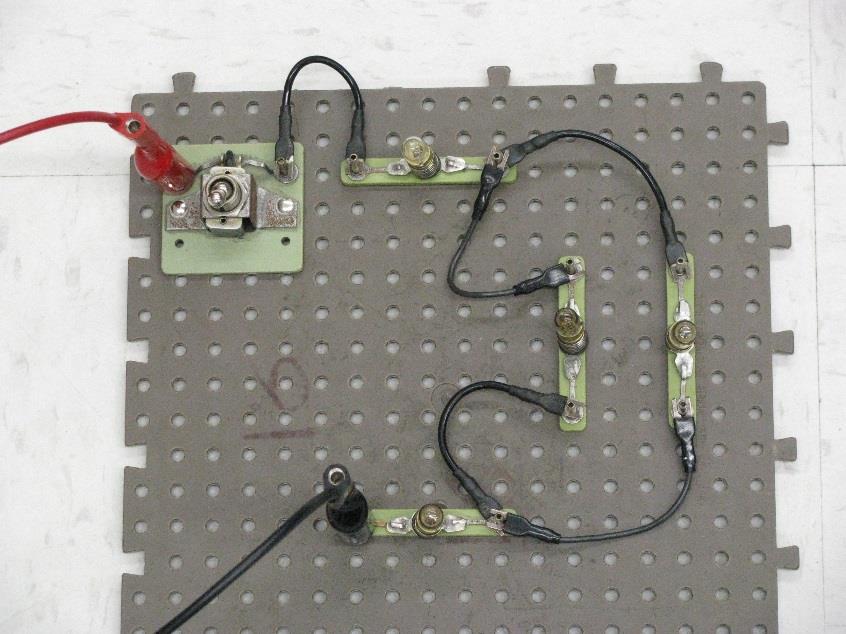
The circuit in figure 4.4 will show that the current that flows into a junction equals the current that flows out of the junction. Connect the following circuit and get an instructor to check your wiring and initial here: _____________
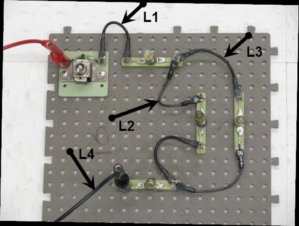
L1
+
L2
L3
12V
L4
Figure 4.4
2.
Turn on the DC supply and set it at 12 V.
In this circuit all of the current flows through the switch and L1. L1 shines brightly because the current is high. The current is split between L2 and L3
and they are dimmer because each lamp has roughly half of the current. The currents combine then flow through L4 and it shines brightly because the current is high. In the next section we’ll measure these currents.
29
Part 4 – Using an In-line Ammeter
1.
Before we use the in-line ammeter we’ll study its characteristics. We’ll use a bench meter as our ammeter, set the bench meter to measure DC current on the 200 mA range. Plug a red banana lead into the red ‘mA’ terminal and a black banana lead into the black ‘common’ terminal.
2.
Use another multimeter to measure the resistance of the ammeter and leads and record here: _____________. (You should find that the in-line ammeter has very low resistance – it is a conductor. We must be careful when we
connect an in-line ammeter to a circuit, as we would with any
conductor! )
3.
It will be easiest to connect the ammeter if the circuit is connected exactly as shown below, change your circuit so it matches this photo.
Figure 4.5
4.
Now we’ll measure the current through each of the lights. To measure the current in a light we connect the ammeter in series with the light. Turn the power off to the circuit and remove the wire in series with L1 as shown in Figure 4.6.
30
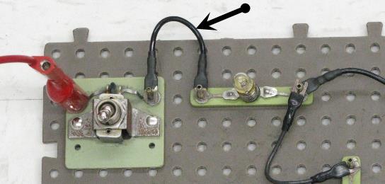
Figure 4.6
5.
Replace this wire with the ammeter and leads (recall that the ammeter is a conductor).
6.
Turn on the power and record the current in Table 4.1. A positive reading indicates that the current flows from the ammeter’s red terminal to the black terminal, a negative reading indicates a flow in the opposite direction.
7.
Remove the ammeter and replace the wire.
31
8.
Follow a similar method to measure the current in the other lights. The figure below shows which wire to remove and replace with the ammeter.
Figure 4.7
Table 4-1
Light
Current
L1
(mA
)
L2
L3
L4
9.
You should find that the currents through L1 and L4 are equal. This is because they are in series. Add the currents through L2 and L3 and record here: ___________. You should find that this combined current is equal to the current through L1 and L4.
10.
The in-line ammeter isn’t used much as a troubleshooting tool because it is so inconvenient to use. The voltmeter is the primary troubleshooting tool and the ohmmeter is the secondary troubleshooting tool.
32
Part 5 – Modified Circuit
1.
Turn off the power and add a wire in parallel with L2 and L3 as shown in figure 4.8.
L1
+
L2
L3
12V
L4
Figure 4.8
2.
Turn on the power. Current now flows easily through the low resistance wire instead of L2 or L3. As a result very little current flows through L2 or L3, not enough to light them. Because this new path permits current to more easily flow from L1 to L4 the current through the circuit increases and L1 and L4 are brighter.
33
