
5 FUNDAMENTALS OF ELECTRICITY
Part 6 – Clamp-on Ammeter
1.
A clamp-on ammeter is very convenient to use and it is often used to check the load on motors.
2.
Set the dial on the current clamp meter to the 200 A position. At this setting the meter can measure currents up to 200 A.
3.
Plug the kettle into the receptacle and measure the individual currents in the hot, neutral and ground wires and record in Table 4-2.
4.
Measure the current in both the hot and neutral wires and record in Table 4-2.
Unplug the kettle after taking these readings.
Table 4-2
Wire
Current (A)
Hot
(Black)
Neutral
(White)
Ground
(Green)
Hot & Neutral (Black & White)
5.
Replace all the components used in this lab and complete the following questions.
6.
Get an instructor to check your results ______________ .
34
Questions
Mark:__________/16
*Assume all switches are closed.
1.
Consider the following circuits:
Original Circuit:
L1
+
12V
L2
L3
Modified Circuit:
L1
+
12V
L2
L3
Will the lamps will be brighter, the same, or dimmer when the circuit is modified (circle the correct answers).
L1:
brighter
same
dimmer
L2:
brighter
same
dimmer
L3:
brighter
same
dimmer
35
2.
Consider the following circuits:
Original Circuit:
L1
+
L2
L3
12V
L4
Modified Circuit:
L1
+
L2
L3
12V
L4
Will the lamps will be brighter, the same, or dimmer when the circuit is modified (circle the correct answers).
L1:
brighter
same
dimmer
L2:
brighter
same
dimmer
L3:
brighter
same
dimmer
L4:
brighter
same
dimmer
36
3.
Consider the following circuits:
Original Circuit:
L1
+
L2
L3
12V
L4
Modified Circuit:
L1
+
L2
L3
12V
L4
Will the lamps will be brighter, the same, or dimmer when the circuit is modified (circle the correct answers).
L1:
brighter
same
dimmer
L2:
brighter
same
dimmer
L3:
brighter
same
dimmer
L4:
brighter
same
dimmer
37
4.
In the following circuit, if the current through L2 is 1A and the current through L3 is 1A, what is the current:
a. through L1? __________
b. through L4? __________
c. supplied by the DC source? __________
L1
+
L2
L3
12V
L4
5.
What value of current do you expect to read if you place a clamp meter around: a. both the hot and neutral conductors of a power cord? __________
b. the ground cable? __________
38
LAB 5 – OHM’S LAW
Objective:
Study the relationship between VOLTAGE, RESISTANCE and CURRENT in an electrical circuit.
Information:
Ohm’s Law may be generalized as follows:
I = E / R
I = E/R states that current in a resistor is directly proportional to the voltage across the resistor and inversely proportional to the resistance R, where I is expressed in amperes, E in volts, and R in ohms.
Measurement Accuracy
Measurement errors are unavoidable. Multimeters have measurement error specifications and components have tolerance specifications.
Please measure the values of the resistors you will use in this lab procedure and then use the measured value of resistance for the calculations in this lab.
We will not track errors during this procedure as we are focused on ohm’s law and not measurement inaccuracies. Expect a 10% tolerance between measured values and calculated values.
Materials:
Multimeters, bench and hand-held
1 – 1 k resistor
1 – 1.5 k resistor
1 – 3.3 k resistor
1 – 6.8 k resistor
1 – SPST switch (Two terminals)
Alligator Clips
Breadboards and Connecting Wires
Reference:
Lecture Notes, Class Webpage
39


Procedure:
1.
Measure and record below the value (including units) for these four resistors: R1 (1 k) =
___________
R2 (1.5 k) =
___________
R3 (3.3 k) =
___________
Fluke8010A
–
+
–
A
+
0.000
R4 (6.8 k) =
___________
Measured values may vary within component tolerance.
2.
Connect the circuit as shown in the schematic Figure 5-1
Figure 5-1
3.
Apply power and with switch closed adjust voltage control until 6 Volts is measured across the resistor with a hand held voltmeter.
4.
Record the current (I) measured by the ammeter in table 5-1.
Table 5-1
R
1000 Ohms
E
6 V
8 V
10 V
12 V
14 V
I (mA)
E / I (Ohms)
5.
Measure and record in turn, the current (I) at each of the voltages setting shown in table 5-1 for R = 1000 ohms.
6.
Calculate the ratio E/I for each corresponding value of E and I and record in table 5-1. When calculating current values use measured resistance values.
7.
Using the OHM’S LAW formula, calculate the current you would expect in the circuit when R = 1000 and E = 9 Volts; E = 18 Volts. Ensure that you use actual measured voltage and resistance for your calculations. Record the 40
computed values in table 5-2. Measure and record currents for the two voltage values.
Table 5-2
Formula Test
E
9 V
18 V
I (mA)Calculated
I (mA)Measured
8.
Turn off the power supply then replace the 1 k resistor with 1.5 k resistor.
9.
Follow the same experimental procedure in steps 4 and 5 for each value of voltage in table 5-3. R = 1.5 k.
41
Table 5-3
R = 1,500 Ohms
E
8 V
12 V
16 V
18 V
20 V
I (mA)
E / I (Ohms)
10.
Replace 1.5 k resistor with 3.3 k resistor and again repeat experimental procedure for each value of voltages shown in table 5-4.
Table 5-4
R = 3,300 Ohms
E
12 V
16 V
20 V
24 V
I (mA)
E / I
(Ohms)
11.
Repeat the experimental procedure for the 6.8 k resistor using Table 5-5.
Table 5-5
R = 6,800 Ohms
E
16 V
20 V
24 V
28 V
I (mA)
E / I (Ohms)
12.
Using ohm’s law, calculate the current you would expect in the circuit when R = 6,800 and E = 18 Volts; E = 26 Volts.
Record the computed values in table 5-6.
Table 5-6
42
Formula Test
E
18 V
26 V
I Computed (mA)
I Measured (mA)
13.
Measure currents for the two voltage values and record in table 5-6.
43
Questions:
1.
For a constant value of R, what is the effect on I if E is doubled?
2.
For a constant value of E, what is the effect on I if:
A)
R doubled?
__________________________________________
B)
R halved?
__________________________________________
3.
An instrumentation sensor provides a signal that varies between 4mA and 20mA.
A) If the sensor is connected to a 250Ω resistor, what voltage would you expect to measure across the resistor when the sensor is supplying 14.4mA?
B) What would be the minimum voltage you would measure across the 250 Ω resistor?
C) What would be the maximum voltage you could measure across the 250 Ω resistor?
4.
What is the resistance of an electric heating element on a stove that draws 5A from a 110V source?
44
LAB 6 – SERIES & PARALLEL CIRCUITS
Objectives:
1.
Investigate and compare the features of series and parallel circuits.
Materials:
1 – Bench Meter
1 – DC Power Supply
1 – Hand held multimeter
1 – 330 , 2W, 10% Resistor
1 – 470 , 2W, 10% Resistor
1 – 1.2 k, 2W, 10% Resistor
1 – 2.2 k, 2W, 10% Resistor
1 – 3.3 k, 2W, 10% Resistor
1 – 4.7 k, 2W, 10% Resistor
1 – 5.6 k, 2W, 10% Resistor
1 – 10 k, 2W, 10% Resistor
1 – 1 Amp Fuse with Holder
1 – SPST Switch (two terminals)
Breadboards and Connecting Wires
Information:
Record all the digits that are reported by your instruments to maintain the highest precision during this experiment.
Reference:
Class notes
45
Procedure:
A.
DETERMINING RT FOR SERIES CONNECTED RESISTORS. (METER)
1.
Use your hand held multimeter to measure the values of resistors. Record results in Table 6-1.
Table 6-1
Rated Value,
330
470
1.2k
2.2k
3.3k
4.7k
5.6k
10k
Ohms
Measured Value,
Ohms
2.
Connect the 330Ω and the1.2 kΩ resistor in series combination 1.
3.
Using the hand held multimeter, measure the total resistance of combination 1. Record in Table 6-2.
Table 6-2
Combination
Rated Value (Ohms)
RT (Ohms)
Computed Value
Measured Value
R1 + R2 + …+ RN
1
330
1.2k
X
X
X
2
330
470
1.2k
2.2k
X
3
330
470
1.2k
2.2k
3.3k
General Formula: RT =
4.
Repeat the procedure in steps 2 and 3 for the remaining resistor combinations in Table 6-2.
5.
Calculate the sum of the measured values of each combination and record in Table 6-2 computed value column.
46
B.
DETERMINING RT FOR SERIES CONNECTED RESISTORS (CIRCUIT)
1.
Ensure the power supply is set to 0V.
2.
Connect the 330Ω and 1.2 kΩ resistors in series combination 1 as per Figure 6-1.
1A
+ mA
330 R
+
D.C. Variable
V
Power Supply
1.2 K
Figure 6-1
3.
Close switch and adjust power supply for 10 volts.
4.
Measure total current IT. Record in Table 6-3.
Table 6-3
Combination
Source(E) V
Current(IT) mA
RT = E/I Ω
Computed Value R1 + R2 + …+ RN
1
2
3
General Formula: RT =
5.
Repeat steps 1, 2 and 3 for each of the remaining resistors combinations.
6.
Compute and record the RT for each series combination in Table 6-3.
47
C.
SERIES VOLTAGE DROP RELATIONSHIP
1.
Connect four resistors in series as shown in Figure 6-2.
1A
+
mA
330 R
+
D.C. Variable
Power Supply
470 R
2.2 K
1.2 K
Figure 6-2
2.
Apply power and with hand held multimeter adjust power supply for 10
volts.
3.
Close switch and read the current that is flowing in the circuit and record below:
IT = ___________ mA
VERIFY YOUR ANSWER USING OHM’S LAW.
I = E/RT
Calculated IT = ___________________________________________
48
4.
Using the measured resistance values of each resistor, and the measured current value, calculate the VOLTAGE DROP of each resistor around the circuit.
*The voltage drop across a resistor is equal to I x R (V = IR).
V1 = ____________ V2 = ____________
V3 = ____________ V4 = ____________
5.
Now add the four voltage drops computed (Eapplied = V1 + V2 + V3 + V4).
Total Voltage Drops = ____________
6.
Using the hand held multimeter measure the voltage drop across each of the four resistors.
V1 = ___________ V2 = ____________
V3 = ___________ V4 = ____________
7.
Add the four voltage drops measured (Eapplied = V1 + V2 + V3 + V4).
Total Voltage Drops = ___________
8.
Now using the actual applied voltage and the current measured in step 3, compute the total resistance of the circuit (RT = E/I).
RT (computed) = ___________
9.
DISCONNECT POWER SUPPLY from the circuit. Using hand held multimeter measure and record the total resistance of the circuit.
RT (measured) = ___________
49
D.
PARALLEL CIRCUIT
1.
Connect the parallel circuit combination as per Figure 6-3.
2.
Ensure the Power Supply is set to 0 volts.
1A
+
mA
+
3.3 K
D.C. Variable
2.2 K
10 K
Power Supply
Figure 6-3
3.
Close switch and adjust power supply for 10 volts. Maintain this voltage level under load until you have completed measurements.
4.
Measure and record the total current (IT) in Table 6-4.
NOTE: When calculating current values, use MEASURED resistance values.
50
Table 6-4
Rated Value
Measured Values
Computed Values
Combination
Step
s
Ohms
Volts
mA
mA
Ohms
R1
R2
R3
E
IT
I1
I2
I3
Total Current
Total
IT = I1 + I2 + I3
Resistanc
e
RT = E/IT
4
2,200
3,300
10,000
1
to
—
3,300
10,000
X
12
—
—
10,000
X
X
13
3,300
4,700
5,600
2
to
—
4,700
5,600
X
14
—
—
5,600
X
X
15
4,700
5,600
10,000
3
to
—
5,600
10,000
X
16
—
—
10,000
X
X
5. Measure and record the individual branch currents I1, I2 and I3 as per Figure 6-3.
(Remember that a current meter is connected in SERIES with the resistive load).
You will need to alter circuit connections to facilitate these current measurements.
6. Calculate Total Current by adding I1, I2 and I3 and record in Table 6-4.
7. Compute Total Resistance by substituting the measured values of E and IT into RT = E/IT and record in Table 6-4.
8. Remove R1 from the circuit. Measure IT, I2 and I3 and record in Table 6-4.
9. Compute and record RT and IT as in steps 7 and 8.
10. Remove R2 from circuit (R1 is also out). Measure IT and I3 and record Table 6-4.
11. Compute and record RT and IT as in steps 7 and 8.
12. Power off, replace resistors in Combination 1 with those of Combination 2. Then repeat step 4 through 12.
13. Power off, replace resistors in Combination 2 with those of Combination 3
14. Repeat step 4 through 12.
51
15. Referring to Figure 6-4, use the hand held multimeter as an ohmmeter and measure the individual resistances of R1, R2, R3. Be sure that no power supply is connected to the circuit.
16. Connect the circuit as per Figure 6-4 using values of Combination 1 (2.2K, 3.3K
and 10K resistors). Measure the total resistance RT and record in Table 6-3.
2.2 K
3.3 K
10 K
Figure 6-4
Table 6-3
Measured Value, Ohms
Computed Value of RT Ohms
Combination
Steps
R1
R2
R3
RT
Total Resistance
Total Resistance
RT = E/IT
1/RT = 1/R1 + 1/R2 + 1/R3
18-20
1
__
21
22
2
__
23
24
3
__
25
19.
Calculate the Total Resistance by substituting the measured values of R1, R2 and R3 into the following equation:
1 = 1 + 1 + 1
RT R1 R2 R3
20.
Connect a power supply to the circuit and apply 10V to the circuit and measure total current (IT).
21.
Remove R1 and repeat steps 18 to 20.
52
22.
Replace resistors in Combination 1 with those of Combination 2 (3.3K, 4.7K and 5.6K resistors).
23.
Using Combination 2, repeat steps 18 to 21 inclusive.
24.
Replace resistors in Combination 2 with those of Combination 3 (4.7K, 5.6K and 10K resistors).
25.
Using Combination 3, repeat steps 18 to 21 inclusive.
53
Questions:
5.
How do you determine the total resistance of series connected resistors?
6.
How do you determine the total resistance in a parallel resistor network?
7.
In series resistance circuits, the sum of the voltage drops around a closed circuit is equal to:
8.
In a series circuit, what is the relationship between voltage drops across a resistor and the relative size of the resistances?
54
9.
Will three lamps connected in parallel use more or less electric power than two lamps in parallel? Prove with an example using a lamp with R = 10Ω and a supply of 10V.
10.
Will three lamps in series will use more or less power than two lamps in series? Prove with an example using a lamp with R = 10Ω and a supply of 10V.
55
LAB 7 – ELECTRICAL POWER
Objectives:
1.
Study the power relationships in an electrical circuit.
2.
Study internal resistance characteristics for a lamp.
Materials:
1 – DC Power Supply
1 – Bench multimeter
1 – Hand held multimeter
2 – 12 Volt Lamps and Sockets
1 – SPST Switch (Two Terminals)
1 – 1 Amp Fuse with Holder
Breadboard and Connecting Wires
Reference:
Electric Circuits and Machines, Chapter 4.
Procedure:
1.
Using the DC power supply, connect circuit as shown in Figure 7-1.
1A
+
mA
DVM
+
D.C. Variable
+
V
Power Supply
Figure 7-1
2.
Apply power and set the variable DC power supply for 0 volts on your voltmeter.
3.
Complete Table 7-1 for each setting of applied voltage. Remember Units.
Table 7-1
56
ONE BULB ONLY
Applied
Current(I)
Calculated Total
Calculated Total
Voltage(E)
Resistance (R = E/I)
Power (P = EI)
2 v
4 v
6 v
8 v
10 v
12 v
NOTE: As the current in the lamp is increased, the temperature of the tungsten filament rises. This rise in temperature causes an increase in the resistance of the lamp. Most metals behave this way, changing resistance with changing temperature.
4.
Place two 12 volt bulbs in Series as per Figure 7-2.
1A
+
mA
Lamp #1
D.C. Variable
+
Power Supply
Lamp #2
Figure 7-2
5.
Complete Table 7-2 on the next page use a maximum supply voltage of 24 volts DC.
57
Table 7-2 (Both Bulbs)
Applied
Current(I)
Total Calculated
Total Calculated
Voltage (E)
Resistance (R = E/I)
Power (P = EI)
4 v
8 v
12 v
16 v
20 v
24 v
6.
Continue to use Figure 7-2 and complete Table 7-3. For each applied voltage, MEASURE AND RECORD the Voltage Drop (V1) across Bulb #1, the Voltage Drop (V2) across Bulb #2, and the current flowing through the bulbs.
58
Table 7-3
Applied
Voltage Drop
Calculate
Calculate
Current(I)
Voltage(E)
Across Each Bulb
Resistance (R = E/I)
Power (P = EI)
For Each Bulb
For Each Bulb
4 v
V1
B1
V2
B2
8 v
V1
B1
V2
B2
12 v
V1
B1
V2
B2
24 v
V1
B1
V2
B2
7.
Add the first two power figures from Table 7-3 (4 volts applied level).
Total = ___________ watts.
8.
Now compare the total power in Table 7-2 to the power figures in Step 7
(4 volt applied level).
59
Questions:
1.
Name two appliances in your home that operate by converting electricity to heat.
2.
Explain why the resistance of a bulb increased when its power increases?
3.
Write the three formulas for determining power in an electrical circuit.
4.
At the cost of 13¢ per kWH, how much does it cost to burn a 100 Watt lamp for 24
hours?
5.
Compute the power consumed:
A) I = 50 ma, E = 100 v
P = __________ W
B) I = 2 amps, R = 100
P = __________ W
C) E = 100 v, R = 100
P = __________ W
D) E = 50 v, R = 100
P = __________ W
E) I = 6 amps, E = 220 v
P = __________ W
F) I = 6 amps, R = 20
P = __________ W
60
LAB 8 – AC RESISTANCE CIRCUITS
Objective:
1.
Confirm that the same rules apply for AC and DC Resistive Circuits.
Materials:
2 – Multimeters
1 – Variable A.C. Power Source (Variac)
1 – 560, 2W, 10% Resistor
2 – 1000, 2W, 10% Resistor
1 – 1.2K, 2W, 10% Resistor
2 – 2.2K, 2W, 10% Resistor
1 – 3.3K, 2W, 10% Resistor
1 – SPST Switch
Breadboards and Connecting Wires
Reference:
Lecture notes
61
Procedure:
A.
AC SERIES RESISTANCES
1.
Using a multimeter to measure and record in Table 8-1, the individual resistances of the circuit (Figure 8-1).
Table 8-1: Component Data
Measured
Calculated
Resistance Values
Resistance Values
RT
R1
R2
R3
R4
2.
Connect the series circuit given in Figure 8-1. Before connecting the ammeter and supply, measure the total Resistance (RT) of the circuit and record in table 8-1.
R1
S1
560R
mA
F1
1A
R2
1k
65 Volts RMS
R4
R3
3.3K
2.2K
Figure 8-1: Series Circuit
3.
Now apply power and adjust the Variac for 65 Volts RMS. Read and record the total current in the circuit.
IT = ___________
62
4.
Using OHM’s LAW, verify your current reading in step 2. Show your work.
Calculated IT = __________
Table 8-2: Series Circuit Data
Calculated
Measured
Voltages
Voltages
EAPPLIED
V1
V2
V3
V4
5.
Measure the applied voltage and the voltage drops across each of the four resistors. Record in Table 8-2.
6.
Using the measured current and voltage values, calculate the total resistance and the individual resistance of the four resistors. Record in Table 8-1.
7.
Using the measured values of each resistor, calculate the applied voltage and the voltage drops around the circuit. Record in Table 8-2.
63
B.
AC PARALLEL RESISTANCES
1.
Connect three resistors in parallel across the variable A.C. power source.
Insert a current meter in series with the parallel network as shown in Figure 8-2.
S1
mA
I1
I2
I3
F1
1A
30 Volts RMS
R1
R2
R3
1K
2.2K
3.3K
Figure 8-2:Parallel Circuit
2.
Now apply power and adjust power source to 30 Volts RMS. Read the total current IT. Record in Table 8-3.
Table 8-3: Parallel Circuit Data
Measured Currents
Calculated Currents
IT
I1
I2
I3
3.
Place the current meter in series with R1 as shown in Figure 8-2 (R2 and R3 still connected). Read the current through R1. Record in Table 8-3.
4.
Place the current meter in series with R2 as shown in Figure 8-2 (R1 and R3 still connected). Read the current through R2. Record in Table 8-3.
5.
Place the current meter in series with R3 as shown in Figure 8-2 (R1 and R2 still connected). Read the current through R3. Record in Table 8-3.
6.
Calculate the total line current IT and the individual branch currents for Figure 8-2. Remember to use measured voltage and resistance values.
Record in Table 8-3.
64
C.
AC SERIES-PARALLEL RESISTANCES
1.
Connect the series-parallel circuit combination to a variable AC power supply as per Figure 8-3.
R1
2.2 k
S1
mA
R2
1.2 k
R3
F1
1k
1A
R4
R5
R6
60 Volts RMS
560R 1k
2.2 k
R7
3.3 k
Figure 8-3: SERIES / PARALLEL CIRCUIT
2.
Using the step by step procedure for determining series/parallel resistances, calculate the total resistance and total current for the circuit in Figure 8-3. Remember to use measured voltage and resistance values.
RT = ___________
IT = ___________
3.
Using the total current determined in step 2, calculate the voltage drops across each resistor in Figure 8-3 and enter their values in Table 8-4.
(Use measured resistance values).
Table 8-4: SERIES/PARALLEL CIRCUIT DATA
V1
V2
V3
V4
V5
V6
V7
Calculated Voltage Drops
Measured Voltage Drops
4.
Close switch and adjust AC power supply for 60 volts rms.
65
5.
Measure the voltage drops across each of the resistors. Record in Table 8-4.
6.
Measure the total and individual branch currents of the series-parallel circuit. Record in Table 8-5.
Table 8-5: SERIES/PARALLEL CIRCUIT DATA
Measured
IT
I1
I2
I3
I4
I5
I6
I7
Currents
66
Questions:
1.
State the formulas for finding current, voltage and total resistance in a series circuit.
2.
State the formulas for finding current, voltage and equivalent resistance in a parallel circuit.
3.
State any appreciable differences between AC resistance circuits and DC resistance circuits.
67
LAB 09 – INDUCTIVE CIRCUITS
Objective:
1.
Determine the effect that inductance has in electrical circuits.
Information:
LENZ’s LAW: A changing value of current in a coil induces a Counter EMF or back EMF, which opposes the change of current.
In DC circuits, the effects of inductance occurs only when there is a change in current value, such as turning the circuit “on” or “off”. In AC circuits, the current is constantly changing its value and a counter emf is continuously present which opposes the applied source voltage and thus the current flow. Inductance may be defined as that “property of a circuit which resists a change in current flow”.
The inductors used in this lab are rated for 7H at full current. We use less current then that maximum during this lab. The calculations performed in this lab will indicate an inductor of a larger value. A large error when determining the value of the inductor is expected.
Materials:
1 – Handheld multimeter
1 – Bench top multimeter
1 – Variable DC Power Supply
1 – 7 Henry Coil (Choke)
1 – 500Ω Variable Resistor or 1kΩ Variable Resistor
1 – switched power cord with fuse
1 – SPST Switch
1 – SPDT Switch
1 – Variable AC Power Source (Variac)
1 – Breadboard and Connecting Wires
1 – 10 Ohm Resistor
Reference:
Lecture notes
68
Procedure:
A.
EFFECT OF A COIL (CHOKE) IN A DC CIRCUIT
1.
Measure and record the resistance of the 7 Henry Coil (choke).
Rcoil = ___________ ohms
2.
Adjust the 500 OHM POT (variable resistor) to have the SAME resistance as the 7 Henry Choke.
Rvariable = ___________ ohms
3.
Connect the circuit according to the schematic in Figure 09-1.
Figure 09-1
HAVE INSTRUCTOR CHECK BEFORE PROCEEDING.
4.
Adjust switch S2 so the variable resistor R is in the circuit.
5.
Close the S1 switch. Turn power on and adjust the DC Power Supply for 10 volts DC.
6.
Read and record the current through the variable resistor.
DO NOT VARY SUPPLY VOLTAGE.
Iresistor = _______________________
7.
Adjust switch S2 so that the coil is in the circuit. The voltage across the coil should be the same as was across the resistor. Record the voltage E.
E = ___________ Volts
8.
Measure and record the current flowing through the coil.
Icoil = _____________________
69
B.
EFFECT OF A COIL IN AN AC CIRCUIT
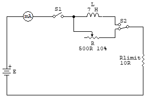
1.
Connect the schematic circuit in Figure 09-2. Use an isolation transformer and a variac for the AC source, AC line cord with an inline fuse for F1 and ensure the DMM is set for AC current measurement.
L
S1
7 H
mA
S2
F1
1A
R
500R 10%
Rlimit
10R
10 Volts RMS
Figure 09-2
NOTE: HAVE INSTRUCTOR CHECK BEFORE PROCEEDING.
2.
Apply power and adjust the source for 10 volts AC. Record the current through the variable resistor R. DO NOT VARY SUPPLY VOLTAGE.
Iresistor = ___________ mA = __________ A
3.
Switch the coil in the circuit, ensure the source is 10 volts AC. Record the current flowing through the coil L.
Icoil = ___________ mA = __________ A
4.
Leave the coil switched in the circuit. Adjust the source voltage to establish each of the currents shown in Table 09-1. Record the applied voltage at each current level. Make sure you do not switch in the resistor when the voltage is not 10V AC.
Table 09-1
5 mA
10 mA
15 mA
20 mA
VSOURCE (Volts)
XL = V/I (Ohms)
NOTE: Knowing the voltage across the COIL and the current through the COIL, one can calculate the COIL’S AC opposition known as inductive reactance (XL).
70
5.
CALCULATE the reactance for each current level in Table 09-1.
(XL = VSOURCE / I).
6.
Calculate the average value of XL. Using this average value, calculate the inductance of the coil in Henries. (XL = ωL = 2πfL Ω)
Questions:
1.
Drawing from the data collected during this lab, explain any difference between the amount of direct current and the amount of alternating current flowing through the coil when the supply voltage was 10V?
2.
State in your own words the property of electrical inductance.
3.
Describe an application for an inductor in either DC or AC operation.
71
LAB 10 – CAPACITORS
Objective:
1.
Determine the effect capacitance has in electrical circuits.
Information:
A capacitor consists of two parallel metallic plates separated by an insulating material called a dielectric. The dielectric may be air, waxed paper, mica, ceramic or other materials. A capacitor blocks the flow of DC, but only partially impedes the flow of AC. There are hundreds of different types and values of capacitors designed for specific applications.
Capacitance is a measure of the amount of charge which a circuit or device can store in the dielectric between two conductors when a given voltage is applied.
Capacitance is measured in Farads.
Many large capacitors retain their charge after the power has been turned off.
These capacitors should be discharged by shorting their terminals together with an insulated screwdriver or other conductor. If this is not done, these voltages may destroy test equipment and might give a shock to anyone working on the equipment.
Materials:
1 – Variable DC Power Supply
1 – Variable AC Power Supply (Variac)
1 – UEI DL389 Multimeter
1 – Benchtop Digital Multi Meter (DMM)
1 – 1.0F Capacitor, 600 Volts
1 – 20F Capacitor, 450 Volts (Electrolytic)
1 – 40F Capacitor, 450 Volts (Electrolytic)
1 – Miniature Lamp and Socket
1 – SPST Switch
Breadboard and Connecting Wires
Don’t use fuses in the circuit for this lab. The DC supply is protected with a current limit and the Variac has the fuse built in.
Reference:
Lecture notes.
72
Procedure:
It takes a couple of seconds for the multimeter to settle on a measured value.
You should use alligator clips to secure the terminals to capacitor. When using hand-held probes, intermittent connection may yield inconsistent results.
1.
Measure the value of the capacitors using the capacitor test feature of the UEI DL389. Capacitance is displayed as the lower value of the display in µF.
Rated Capacitor Value
Measured Capacitance
1.0 µF
20 µF
40 µF
2.
Connect the 20F electrolytic capacitor in series with a miniature lamp across a DC power source as per Figure 10-1. (Observe the correct POLARITY when using electrolytic capacitor).
(Do not connect shorting wire yet).
S1
mA
L1
F1
1A
C1
+ V1
20uF
Shorting Wire
Figure 10-1
73
3.
Apply power and adjust the voltage for 10 volts. Does the lamp light?
__________. Explain.
4.
With the power still on, short out capacitor with a connecting wire. What effect does this have on the lamp?
5.
Connect the circuit shown in Figure 10-2. (Set the ammeter to AC) S1
mA
F1
L1
1A
12 Volts RMS
C1
20uF
Figure 10-2
6.
Apply AC power and observe effects on the lamp. Does the lamp light?
__________ Explain.
7.
Replace the 20F capacitor with a 40F capacitor. Does the lamp light?
__________ Does it glow brighter or dimmer than before?
74
8.
Connect the 20F capacitor to power supply as per Figure 10-3.
Do not connect the shorting wire yet.
S1
mA
+ V1
C1
Shorting Wire
20uF
Figure 10-3
9.
Turn on the switch, and adjust the power supply from 0 to 15 volts DC.
10.
Measure the DC voltage across the capacitor.
11.
Keep the meter connected while you turn off the switch.
12.
Describe what happens to the voltage reading of the voltmeter when the switch is turned off.
13.
SHORT OUT the capacitor terminals with connecting wire and describe what happens to the DC voltage across the cap.
75
14.
Connect the circuit given in Figure 10-4. Set V1 at 0V.
S1
mA
+ V1
C1
20uF
Figure 10-4
15.
Adjust milliammeter to read DC.
16.
Turn down the power supply voltage to zero.
17.
Observe the current meter as you slowly increase the voltage to 15 Volts.
Does current continue to flow in the circuit? ___________
For this section, speed of change of the DC voltage is more important than the final voltage value. 25 V should be close to the maximum the DC supplies will produce. Also, the 5 V level is just a coarse target. If you are more concerned with arriving at 5 V that you are about getting there quickly you may not see the effect we are focusing on in this section.
18.
QUICKLY increase the voltage to 25 Volts and observe the direction of current flow.
State direction of flow. ________________________________
19.
Now QUICKLY decrease the supply voltage to 5 volts and observe the direction of current flow – then continue to slowly decrease to 0 volts and observe current flow.
State direction of flow. ________________________________
20.
Explain why in step 17 and 18 current flowed only when the voltages was Increased and Decreased:
76
Questions:
1.
What are the units that capacitors are rated in?
2.
What effect does a capacitor have on DC current?
3.
What could happen if an electrolytic capacitor were connected with opposite polarity?
4.
Which capacitor allows greater flow of AC current (smaller or larger capacitor)?
Please explain why.
77
LAB 11: TRANSFORMERS
Objective:
Determine the relationship between the Primary side and Secondary side of a transformer by considering Resistance, Voltage and Current.
Observe the operation of a transformer under load.
Make proper voltage measurements in a transformer circuit.
Materials
1 – Hand Held Multimeter (Fluke 70 or equivalent)
1 – Bench Top Multimeter (Fluke 8000A)
1 – Transformer, Hammond 167L12
1 – 25 75W tapped power resistor
1 – Switched line cord with fuse
2 – 12 Volt Lamp
1 – SPST switch
4 – Alligator clips for banana leads
Misc. Connecting wires as required.
78
