6 FUNDAMENTALS OF ELECTRICITY
Introduction
There is a limited supply of 25Ω resistors. It is recommended that you do this lab with a partner.
Transformers are used in distribution systems to bring power from the generating stations into the customer’s location. Transformers are also used in control circuits, like those found in gas appliances.
Transformers are constructed from two sets of windings called the primary and the secondary windings. These windings are wrapped around an iron core to improve efficiency.
Step-down transformers bring the voltage down to an easily managed level like 24V
AC. 24V AC controls are smaller, less expensive, and most importantly safer to work with.
If you have difficulty distinguishing between the primary and secondary windings of the transformer in this lab, please ask the instructor for assistance.
Procedures
1. Use a multimeter to measure the resistance of the primary and secondary windings of the transformer. Enter the results of your tests in the table below.
Resistance of the primary
Ω
Resistance of the
Ω
secondary
Table 1 – Transformer resistance
2. You should notice that the resistance of the primary windings is larger than the resistance of the secondary windings.
79
The wire used for the primary winding is longer than the secondary winding. The wire used for the primary winding is also thinner than the secondary wire.
120V
Primary
Secondary
80
3. The secondary voltage is dependent on the primary voltage and the turns-ratio.
Now we will determine the turns-ratio of the transformer.
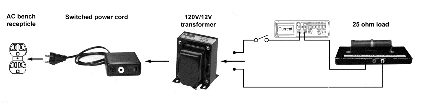
Connect the switched power cord to the primary side of the 120/12V transformer. Use alligator clips on the end of banana leads for this connection.
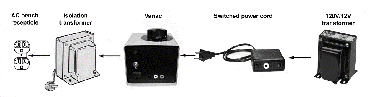
Plug the switched power cord into the adjustable Variac transformer.
Plug the Variac transformer into the large black isolation transformer.
Plug the large black isolation transformer into the 120-volt receptacles located on the bench.
4. Turn the variac dial fully counter – clockwise to zero and turn on the Variac power switch.
5. Turn the Variac knob to adjust the voltage on the primary side of the transformer to the values in table 2 and record the corresponding secondary voltages.
Note: You must measure the transformer primary voltage with a multimeter while you adjust the dial, the Variac dial does not indicate output voltage.
Primary
Secondary Voltage
Turns-ratio
Voltage
60 Volts
VAC
90 Volts
VAC
120 Volts
VAC
Table 2 – Unloaded voltage measurements
6. Calculate the turns ratio for each of the rows in table 2 using the turns ratio equation below. Vp is the primary voltage, and Vs is the secondary voltage.
VP
Turns R
atio
VS
7. Turn off the power. Disconnect the Variac and place it aside.
81