
1 FUNDAMENTALS OF ELECTRICITY
BASIC ELECTRICITY FOR
TECHNOLOGY PROGRAMS
Tim Schneider, A.Sc.T.
Instructor, Electronics Systems Engineering Technology
School of Mining, Energy, and Manufacturing
Saskatchewan Polytechnic

Fundamentals of Electricity by Tim Schneider, A.Sc.T is licensed under a Creative
Commons Attribution 4.0 International License, except where otherwise noted.
All images were taken at Saskatchewan Polytechnic unless otherwise noted. All figures and tables were created at Saskatchewan Polytechnic unless otherwise noted.
2
LAB 1: MEASURING RESISTANCE
Objectives:
Work safely on electrical equipment
Observe concepts of resistance, continuity, conductors, and insulators
Measure resistance with a multimeter.
Materials:
Multimeter with probes
Copper wire spools:
wet sponge
14 AWG 300 meters
wood
16 AWG 300 meters
20 AWG 300 meters
22 AWG 75 meters
22 AWG 1500 meters
Information:
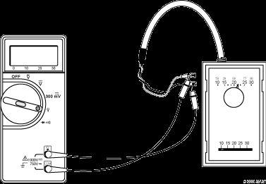
In this lab we will measure the resistance of common equipment using a hand-held multimeter.
When the resistance you are measuring is greater than 32MΩ (32,000,000 ohms), the Fluke 70 will display O.L (over limit).
You must ensure to apply the proper amount of pressure on the probe tips when you are making a resistance measurement. If the probes are just resting there will not be a good connection and the meter will not read the correct resistance. If you push too hard you could damage the probe or slip and injure yourself.
3
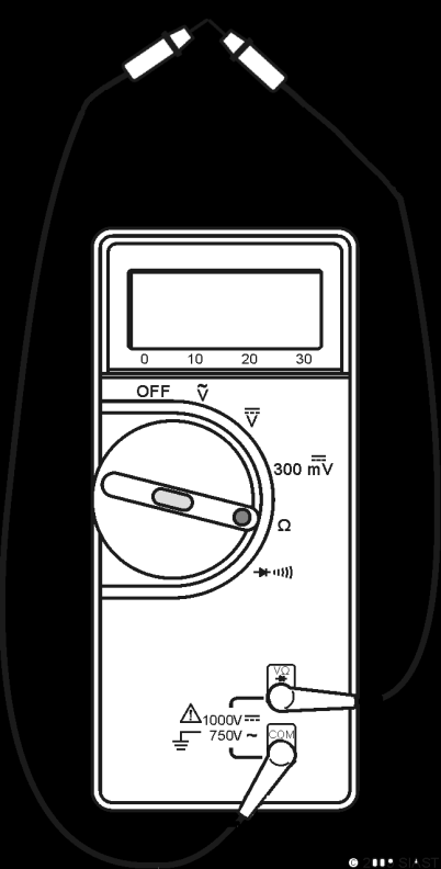


1 ) I n s e r t t h e r e d a n d b l a c k
m e t e r l e a d s i n t o t h e
m e t e r a n d k e e p t h e
t i p s s e p a r a t e d .
2 ) S e t m e t e r d i a l t o Ω .
3 ) R e c o r d t h e r e a d i n g o n
t h e m e t e r i n f i g u r e 1 A .
4 ) W h a t d o e s t h i s m e t e r
r e a d i n g m e a n ?
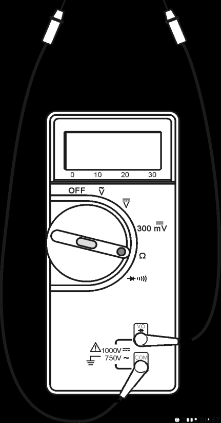
5 ) T o u c h t h e t i p s o f t h e
m e t e r l e a d s t o g e t h e r
a n d r e c o r d t h e r e a d i n g
o n t h e f a c e o f t h e
m e t e r i n f i g u r e 1 B .
F i g u r e 1 A
F i g u r e 1 B
6 ) H o l d t h e m e t a l t i p s o f
t h e m e t e r l e a d s t i g h t l y
i n y o u r d r y f i n g e r s .
7 ) R e c o r d t h e a v e r a g e
v a l u e i n F i g u r e 2 A .
8 ) W e t y o u r h a n d s o n a w e t
s p o n g e , p l e a s e d o n o t
l i c k y o u r f i n g e r s .
9 ) H o l d t h e m e t a l t i p s o f
t h e m e t e r l e a d s t i g h t l y
w h i l e y o u r f i n g e r s a r e
w e t .
1 0 ) R e c o r d t h e a v e r a g e
v a l u e i n f i g u r e 2 B .
F i g u r e 2 A
F i g u r e 2 B
4


1 1 ) W i t h o u t t o u c h i n g t h e
m e t a l p r o b e t i p s ,
m e a s u r e t h e
r e s i s t a n c e o f w o o d .
W r i t e t h e r e a d i n g i n
F i g u r e 3 A .
1 2 ) N o w , t o u c h t h e m e t a l
t i p s o f y o u r m e t e r
l e a d s w i t h y o u r
f i n g e r s w h i l e y o u
m e a s u r e t h e
r e s i s t a n c e o f t h e
w o o d . R e c o r d t h e
r e a d i n g i n f i g u r e 3 B .
1 3 ) H o w i s t h e r e a d i n g
a f f e c t e d w h e n y o u
t o u c h t h e m e t e r
l e a d s ?
F i g u r e 3 A
F i g u r e 3 B
1 4 ) M e a s u r e a n d r e c o r d t h e r e s i s t a n c e o f t h e t h r e e s p o o l s o f w i r e p r o v i d e d .
3 0 0 m
3 0 0 m
3 0 0 m
1 4 A W G
1 6 A W G
2 0 A W G
___________
___________
___________
1 5 ) D o e s t h i n n e r w i r e h a v e m o r e o r l e s s r e s i s t a n c e t h a n t h i c k e r w i r e ?
M o r e
L e s s
5
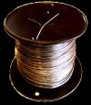

1 6 ) M e a s u r e t h e r e s i s t a n c e o f t h e t w o 2 2 A W G s p o o l s o f w i r e p r o v i d e d . R e c o r d t h e r e s i s t a n c e b e l o w .
7 5 m 2 2 A W G
1 5 0 0 m 2 2 A W G
___________
___________
1 7 ) D o e s l o n g e r w i r e h a v e m o r e o r l e s s r e s i s t a n c e t h a n s h o r t e r w i r e ?
M o r e
L e s s
1 8 ) M e a s u r e t h e r e s i s t a n c e o f o n e o f t h e c o i l s o f w i r e a n d t h e n t o u c h t h e w i r e w h i l e y o u a r e m e a s u r i n g t h e r e s i s t a n c e . D o e s t h e v a l u e o f r e s i s t a n c e c h a n g e w h e n y o u a r e t o u c h i n g t h e w i r e ?
N o c h a n g e o r
b i g d i f f e r e n c e
v e r y l i t t l e c h a n g e
( m o r e t h a n 1 0 %
( 0 t o 1 0 % c h a n g e )
c h a n g e )
6
1 9 ) M e a s u r e r e s i s t a n c e b e t w e e n s p e e d w i r e s o f t h e m u l t i – s p e e d P S C m o t o r . R e c o r d a l l o f t h e p o s s i b l e c o m b i n a t i o n s o f r e s i s t a n c e i n t h e f o l l o w i n g c h a r t : B l a c k
B l u e
R e d
Y e l l o w
G r e e n
M o t o r
F r a m e
B l a c k
B l u e
R e d
* U s e t h e t h e r m o s t a t f o r t h e f o l l o w i n g s t e p . R e c o r d y o u r m e t e r r e a d i n g s i n t h e t a b l e b e l o w . T h e r m o s t a t o p e r a t i o n p r o v i d e s e i t h e r a c l o s e d s w i t c h ( O n ) o r o p e n s w i t c h ( O f f ) *
2 0 ) A d j u s t t h e r m o s t a t :
i ) s o i t i s c a l l i n g f o r h e a t ( > 3 0 d e g r e e s ) .
i i ) s o i t i s n o t c a l l i n g f o r h e a t ( < 1 0 d e g r e e s ) 2 1 ) M e a s u r e t h e r e s i s t a n c e b e t w e e n t h e r e d a n d w h i t e w i r e s .
2 2 ) R e c o r d t h e r e s i s t a n c e b e t w e e n t h e r e d a n d w h i t e w i r e s .
7
Thermostat Resistance calling for heat
Thermostat Resistance not calling for heat
8
2 3 ) R e m o v e a f u s e f r o m t h e s t a n d i n g p i l o t f u r n a c e t r a i n e r .
M e a s u r e a n d r e c o r d t h e r e s i s t a n c e o f t h e f u s e .
F u s e r e s i s t a n c e = _____________
2 4 ) R e p l a c e t h e f u s e .
Q u e s t i o n s ( c i r c l e t h e b e s t a n s w e r ) :
1 ) T h e r e s i s t a n c e o f a g o o d f u s e i s ?
L e s s t h a n 1 0 0 Ω
L a r g e r t h a n t h e m e t e r c a n m e a s u r e 2 ) T h e r e s i s t a n c e o f a n o p e n s w i t c h i s ?
L e s s t h a n 1 0 0 Ω
L a r g e r t h a n t h e m e t e r c a n m e a s u r e 3 ) W h a t i s t h e r e s i s t a n c e o f a g o o d c o n d u c t o r ?
l e s s t h a n 1 0 0 Ω
1 0 0 Ω – 1 0 k Ω
1 0 k Ω – 1 0 M Ω
4 ) H o w d o e s l e n g t h a f f e c t t h e r e s i s t a n c e o f a w i r e ?
S h o r t e r w i r e s h a v e
N o e f f e c t
L o n g e r w i r e s h a v e
m o r e r e s i s t a n c e .
m o r e r e s i s t a n c e .
5 ) H o w d o e s g a u g e a f f e c t t h e r e s i s t a n c e o f a w i r e ?
T h i n n e r w i r e s h a v e
N o e f f e c t
T h i c k e r w i r e s h a v e
m o r e r e s i s t a n c e .
m o r e r e s i s t a n c e .
9
6 ) W h e n w i l l y o u r b o d y r e s i s t a n c e a f f e c t a r e s i s t a n c e m e a s u r e m e n t ?
W h e n t h e r e s i s t a n c e t o b e
W h e n t h e r e s i s t a n c e t o
m e a s u r e d i s m u c h l o w e r t h a n
b e m e a s u r e d i s m u c h
y o u r b o d y r e s i s t a n c e .
h i g h e r t h a n y o u r b o d y
r e s i s t a n c e .
7 ) W h a t a f f e c t d o e s m o i s t u r e h a v e o n t h e r e s i s t a n c e o f y o u r s k i n ?
M o i s t u r e l o w e r s
M o i s t u r e i n c r e a s e s
r e s i s t a n c e
r e s i s t a n c e
8 ) W h e n y o u t e s t a m u l t i p l e s p e e d P S C m o t o r w h a t l e v e l o f r e s i s t a n c e d o y o u e x p e c t t o m e a s u r e b e t w e e n t h e d i f f e r e n t m o t o r s p e e d w i r e s ?
l e s s t h a n 1 0 0 Ω
g r e a t e r t h a n 1 0 0 Ω
9 ) W h e n y o u t e s t a m u l t i p l e s p e e d m o t o r , w h a t l e v e l o f r e s i s t a n c e d o y o u e x p e c t t o m e a s u r e b e t w e e n t h e m o t o r s p e e d w i r e s a n d t h e m o t o r f r a m e ?
l e s s t h a n 1 0 0 Ω
g r e a t e r t h a n 1 0 0 Ω
10


LAB 2 – RESISTANCE MEASUREMENT
Objectives:
1.
Practice reading the resistance colour code.
2.
Measure resistance using a digital multimeter.
3.
Study the operation of a variable resistor.
Information:
Band 1
Band 2
Band 3
Band 4 (Tolerance)
(Multiplier)
Table 2-1: Resistor Colour Chart
Resistors
Significant Figures
Colour
Multiplier
Tolerance, ± %
1 or 100
–
0
Black
10 or 101
–
1
Brown
100 or 102
–
2
Red
1,000 or 103
–
3
Orange
10,000 or 104
–
4
Yellow
100,000 or 105
–
5
Green
106
–
6
Blue
107
–
7
Violet
108
–
8
Gray
109
–
9
White
0.10 or 10-1
5
–
Gold
0.01 or 10-2
10
–
Silver
–
20
–
No Color
11
Materials:
1 – Digital Multimeter
6 – Assorted Resistors (All different values)
1 – 1.0 kΩ or 5.0 kΩ Potentiometer
Breadboard and connecting leads
References:
Class Notes
Procedure:
A.
FIXED RESISTOR
1.
Place resistors neatly on your breadboard.
2.
Determine the rated value of each resistor from the colour code and record the information in the following table.
Resistor Colour and Value
Measured
Resistor No.
Value
1st Colour
2nd Colour
3rd Colour
4th Colour
Rated Value
Tolerance
1
2
3
4
5
6
3.
Measure the resistance of each individual resistor and record in the table.
NOTE: Be sure you are not touching the metal parts of the probe when you are taking your resistance readings as this may give you a false indication.
12
B.
VARIABLE RESISTORS
1.
Obtain a potentiometer.
a. Place the variable resistor on the breadboard so that the three prongs leading from it are in the same position as indicated in Figure 2-2.
A
C
B
Figure 2-2: Variable Resistor
2.
Turn the shaft of the variable resistor completely counter-clockwise. Place the probes of the multimeter on points A and C.
R = ________ ohms
3.
Now rotate the shaft, leaving the probes on the points A and C. Do you get a change in reading?
4.
Now place the probes on points A and B. Rotate the shaft to approximately halfway between CCW (Counter-clockwise) and CW
(Clockwise).
R = ________ ohms
5.
Now with probes on points A and B, rotate shaft completely clockwise.
R = ________ ohms
6.
Explain the reason for the readings in steps 2 through 5.
13
Questions:
1.
List the colour code for the following resistors (assume 5% tolerance): A) 27 ohms
_________________________________
B) 2200 ohms
_________________________________
C) 39 ohms
_________________________________
D) 560 ohms
_________________________________
E) 33 000 ohms
_________________________________
14
LAB 3 – BATTERIES AND D.C. VOLTAGE MEASUREMENT
Objectives:
1.
Use a multimeter to measure DC voltage.
2.
Measure batteries in series and parallel configurations.
Information:
A.
MEASURING DC VOLTAGE
Measurement of DC voltage is basic in electrical or electronic work. In this experiment, you will use the voltage function of a DMM to measure various dry cell arrangements. Interpretation of your measurements will assist you in determining characteristics of the dry cell arrangements.
Voltage is defined as electrical pressure. It is the difference in electrical pressure between two points. The voltage across two points is measured with a voltmeter.
Therefore you must select the DC voltage function on the DMM.
Generally, the following steps apply for meter setup:
1.
The DMM must be turned on.
2.
The meter test leads should be plugged into the proper inputs. Insert the black lead in the input labelled common and the red lead in the input labelled voltage (V-Ω).
3.
The function switch should be set to DC Voltage.
4.
The test leads are then connected to the circuit under test.
5.
Step the scale or range down until the most accurate voltage value is displayed.
15
B.
DRY BATTERIES
Dry batteries consist of arrangements of primary cells, called “dry cells”. The familiar flashlight “battery” is a dry cell. Individual dry cells produce a low voltage.
By connecting dry cells in a series aiding arrangement, we produce a battery whose voltage is the sum of the dry cell voltages. By connecting two or more dry cells in parallel, we produce a battery whose voltage is the same as that of an individual dry cell. Parallel arrangements increases the amount of available current. Dry batteries usually consist of a series / parallel arrangement of cells. These arrangements support batteries with higher voltage and higher capacity.
Materials:
4 – D Cells (1.5 volts per cell)
1 – Multimeter and Probes
1 – Tray of Connecting Wires
References:
Class Notes
16
Procedure:
A.
BATTERIES IN SERIES
NOTE: If you notice wire getting warm, please disconnect immediately and recheck your circuit.
1.
Measure and record in Table 3-1 the VOLTAGE of each of the individual dry cells supplied.
Table 3-1
Dry Cell #
1
2
3
4
Voltage
2.
Connect cells 1 and 2 in Series as shown in Figure 3-1 or Figure 3-2a.
Measure and record the total voltage in Table 3-2.
NO DATA
DC V
+
+
Figure 3-1
3.
Connect cells 1, 2 and 3 in series as per Figure 3-2b. Measure and record the total voltage in Table 3-2.
17
A
A
A
cell
cell
1
1
cell
cell
cell
2
1
2
cell
cell
cell
3
2
3
cell
B
4
B
B
3-2a
3-2b
3-2c
Figure 3-2: Series Configurations
4.
Now connect the four cells in series as per Figure 3-2c. Measure and record the total voltage in Table 3-2.
Table 3-2
Step No.
2
3
4
Voltage (Volts)
18
B.
BATTERIES IN PARALLEL
1.
Connect two cells in parallel, as shown in Figure 3-3a. Measure and record the voltage in Table 3-3.
A
A
A
cel 1
cel 2
cel 3
cel 1
cel 2
cel 3
cel 4
cel 1
cel 2
B
B
B
3-3a
3-3b
3-3c
Figure 3-3: Parallel Configurations
2.
Connect three cells in parallel as per Figure 3-3b or Figure 3-4. Measure and record voltage in Table 3-3.
NO DATA
DC V
+
+
+
Figure 3-4
19
3.
Connect four cells in parallel as per Figure 3-3c or Figure 3-5. Measure and record voltage in Table 3-3.
NO DATA
DC V
+
+
+
Figure 3-5
+
Table 3-3
Step No.
1
2
3
2 D-Cells
3 D-Cells
4 D-Cells
Voltage (Volts)
20
C.
SERIES PARALLEL CONNECTION
1.
Connect four cells as indicated in Figure 3-6. Measure the voltage from points A to B and record in space provided.
+
+
A
EA-B = ________ volts
B
+
+
Figure 3-6
2.
Now connect cells as per Figure 3-7 and measure the voltage from points A to B. Record voltage reading in space provided.
A
+
+
EA-B = ________ volts
+
+
B
Figure 3-7
21
D.
BATTERIES IN SERIES OPPOSING
1.
Connect two cells in series opposing as per Figure 3-8. Measure and record the voltage reading obtained from points A to B in space provided.
EA-B = _________ volts
+
A
+
B
Figure 3-8
2.
Connect three cells as per Figure 3-9. Measure and record the voltage obtained from points A to B in space provided. Also, indicate relative polarities in spaces below.
EA-B = ________ volts
+
A
A’s polarity is _________
B’s polarity is _________
+
B
+
Figure 3-9
22
3.
Connect four cells as per Figure 3-10. Measure and record the voltage obtained from points A to B in space provided. Also indicate relative polarities in spaces provided
+
EA-B = ________ volts
A
A’s polarity is ________
+
B’s polarity is ________
+
+
B
Figure 3-10
NOTE: Please turn off the meter and return equipment before leaving the lab.
23
Questions:
1.
Name some precautions which must be observed in measuring voltages.
2.
What arrangement of six dry cells would give the maximum life, regardless of voltage?
3.
What arrangement of six dry cells would give the maximum voltage?
4.
Draw the best arrangement of ten 1.5 volt dry cells to give an overall voltage of 7.5 volts.
24
LAB 4: CURRENT
Name ______________________
Objectives:
Understand the flow of electrical current
Measure current with in-line and clamp-on ammeters
Materials:
1 – Fluke 70 multimeter
1 – Fluke 8010 bench meter
1 – DC power supply
4 – 12 V lamps
1 – toggle switch (SPST)
2 – banana plug leads (1 red and 1 black)
2 – alligator clips for banana plug leads
Instructor will setup a station for measuring AC current with a clamp-on meter: 1 – Fluke 30 clamp meter
1 – electric kettle
1 – extension cord with outer jacket removed
Evaluation:
The questions at the end of this lab will be graded and you will get a mark out of 16 possible for this lab.
Background:
Current flows through a circuit. A few simple rules apply:
Current takes the “easiest” path.
The amount of current flowing in a circuit will increase if the amount of resistance in that circuit decreases.
The amount of current flowing into a junction equals the amount of current flowing out of the same junction.
Conventional current flows from the source’s positive terminal through the circuit and back to the source’s negative terminal.
25
Reference:
How to Measure Current using an In-line Ammeter:
Current is measured in units of amps and the symbol for amps is A.
1. Insert the leads into the bench meter, red lead into the red ‘mA’ terminal and black lead into the black ‘common’ terminal.
2. Select AC or DC as appropriate.
3. Select current.
4. Select the 2000 mA range.
5. Turn off power to the circuit.
6. Remove a wire from the circuit and replace it with the ammeter and leads.
7. Restore power to the circuit.
8. Select the lowest range which will display the current to get a reading with the best precision.
26
Procedure:
